Attention! Control arm bushings 3-20-711 unlike the original ones do not have outer metal shell. The installation of these bushings must be done into the outer shells of the old bushings. Do not remove the old outer shells from the control arm. Remove only rubber in any convenient way.
Removal
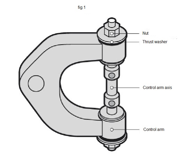
- Unscrew the nuts of the control arm axis, remove the thrust washers. Remove all rubber without removing old outer shells.
- Remove an axis from the control arm.
- Remove the old metal inner sleeves from the control arm axis.
- Inspect the surface of the housing bore of the arm and housing area on the axis, file and polish if any dirt, rust, rubber remains.
Installation
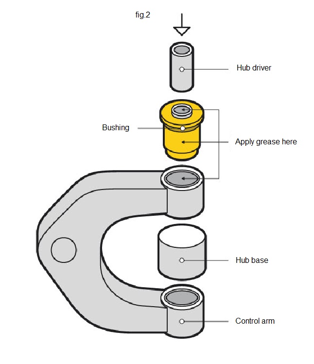
- Choose the hub driver for the installation of bushing. O.D. of the hub driver must be the same as O.D. of the inner metal sleeve. Hub base must be the same diameter as the bushing’s outer metal shell.
- Lubricate a housing bore in the arm and outer surface of the bushing with supplied grease or any other consistent grease (fig. 2).
- Place a control arm upon the hub base into the press.
- Place a new bushing in the housing bore.
- Place a hub driver upon the inner metal sleeve of the bushing.
- Start pressing. Increase the load gradually to make bushing spreading evenly until it fills the housing bore completely.
- Initially the bushing may slip into the housing bore slightly skewed because of the difference in diameters of housing bore and bushing. Due to the resiliency of the bushing, it’s bigger diameter allows to fill the housing bore completely and fix the bushing properly.
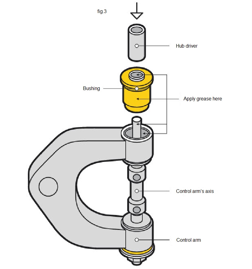
- Insert an axis into the control arm and through the inner sleeve of the bushing. Place a control arm in the press. Press an axis into the inner sleeve of the bushing (fig.3).
- Place second bushing in the housing bore. Place a hub driver upon the inner metal sleeve of the bushing.
- Start pressing, taking in consideration that second bushing will be pressed into the control arm and on the axis simultaneously.
- After the new bushings are pressed in, remove the excess grease. Install the thrust spacers on the axis, screw the nuts.
Attention! After the bushing’s replacement, check the wheel alignment.
Continued overleaf
Starting overleaf
| Possible
problems*
*Are not a result of the parts defects and can’t be considered as a warranty case. |
Inner metal sleeve is torn off. | Control arm bushing without outer metal shell doesn`t slip into the housing bore because of the bulging elastomer. | Bushing is not holding in the housing bore. |
| Wearout of the stabilizer and / or arm’s housing bores. |
|
X
|
|
| Another parts of suspension are worn out. As a result, the load on the bushings is uneven. |
X
|
|
|
| Vehicle was operated in excess of the maximum capacity. |
X
|
|
|
| Grease is washed out over time or the grease was not attached during the installation. |
X
|
|
|
| Inner sleeve or outer shell is not adhered to the elastomer by design specificity. |
X
|
|
|
| Vehicle is raised on and the geometry of suspension is broken. |
X |
|
|
| Bushing was installed without taper that is necessary for the proper installation of the bushings without outer metal shell. |
X
|
||
| Bushing has been trimmed or ground. |
X
|
||
| Wrong choice of the bushing (incorrect OEM). |
X
|
X
|
|
| Sharpened edges of the housing bore were not filed and caused a damage of the bushing during the installation. |
X
|