Attention! Before starting a work of the removing and installation of the control arm bushing with stepped outer metal shell, take note of its placement. If the placement of the bushing is significant for the proper operation, mark the correct position of the bushing in the control arm. Determine the difference of the outer metal shell diameters and the direction of the bushing’s removal from the arm. Remove towards the increase of diameter. Install conversely towards the reduction of diameter.
Removal
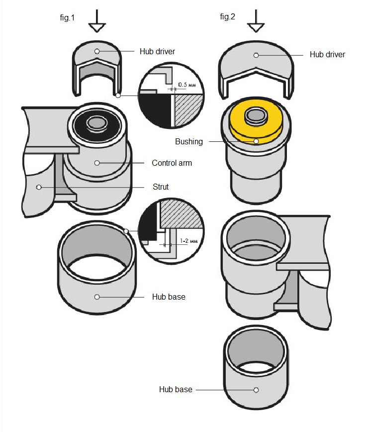
- Choose the metal tubings (hub base and hub driver) for the removal and installation of bushing. O.D. of hub driver must be 0,5 mm. less than O.D. of the outer metal shell (fig.1) to avoid damage of the housing bore and control arm deformation. You should prepare two kinds of hub base. One for removal and another for installation, because we have two different diameters of outer metal shell. I.D. of the hub base must be 1-2 mm. bigger than O.D. of the outer metal shell not to interfere bushing removing. If control arm has a П-shaped profile, use the strut to avoid deformation while removing and installing the bushings.
- Place an arm on a press, supported by the hub base. Place a strut into the arm if it has a П-shaped profile.
- Ensure the correct direction of the bushing removing.
- Place a hub driver upon the bushing.
- Press an old bushing out of the arm increasing pressure gradually to avoid a skewness of the hub driver and deformation of the housing bore and control arm.
- After pressing old bushing out, inspect the surface of the housing bore, clean, file and polish if any dirt, rust, burr.
Installation
- Compare I.D. of the housing bore and O.D. of the bushing’s outer shell. O.D. of the outer shell must exceed I.D. of the housing bore 0,2-0,5 mm. Difference in diameters provides required fixation of the bushing in the housing bore in a result of the outer shell resiliency. If you do not detect the difference in diameters, ensure the correct bushing or change the control arm.
- If marking of old bushing was done, mark new bushing exactly as dismantled one, to provide the correct position of new bushing in the housing bore of the control arm.
- Place a control arm upon the hub base into the press. Insert the strut into the П-shaped arm to avoid deformation and press old bushing out.
- Place a bushing in the housing bore in marked position.
- Ensure the correct direction of the bushing installing.
- Place a hub driver upon the bushing.
- Start pressing. Increase the load gradually to avoid skewness and deformation of hub driver and bushing. While pressing take a control over the alignment of the marks on the control arm and new bushing.
- After the new bushing is pressed in, remove the strut from П-shaped arm, hold the control arm and ensure the correct position of new bushing in the housing bore of the control arm.
Attention! After the bushings replacement, check the wheel alignment.
| Possible
problems* *Are not a result of the parts defects and can’t be considered as a warranty case |
Inner metal sleeve is torn off. | Outer metal shell is torn off. | Elastomer part of the bushing is rifted or damaged. | Bushing is not holding in the housing bore. | Control arm bushing with outer metal shell is deformed while installing in the housing bore. |
| Wearout of the stabilizer and / or arm’s housing bores. |
|
X |
|||
| Housing bore is not cleaned from dust and rust. |
X |
||||
| Another parts of suspension are worn out. As a result, the load on bushings is uneven. |
X
|
X
|
X
|
||
| Vehicle was operated in excess of the maximum capacity. |
X
|
X
|
X
|
||
| Outer shell or inner sleeve is not adhered to the elastomer by design specificity. |
X
|
X
|
|||
| Vehicle is raised on and the geometry of suspension is broken. |
X
|
X
|
X
|
||
| Bushing has been trimmed or ground. |
X |
||||
| Wrong choice of the bushing (incorrect OEM). |
X |
X |
|||
| Sharpened edges of the housing bore were not filed and caused a damage of the bushing during installation. |
X
|
X
|
|||
| Inappropriate tightening of the parts. |
X |
||||
| While the new bushing was pressing in, inappropriate hub driver cut the elastomer that has been torn later. |
X
|
||||
| Bushing was skewed while installing into the housing bore. |
X
|
||||
| Inappropriate hub driver. Uneven distribution of the press force. |
X
|
||||
| Housing bore was damaged during the removal of old bushing. |
X
|